First 8 bit Adder
january 20, 2014
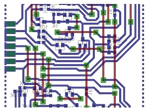
The big modules in the middle are the full-adders, on the right are the half-adders and on the left side the XOR-gates.
(XOR and the half-adders are needed to do the hardware implementation of subtraction)
This was my first build and it ended up with some critical design faults.
It took me about half a year, to find the error in the circuits.
In short, the mistake was in the logic gate design.
I built a full-adder, which can handle negative numbers and is able to add or subtract them.
The problem was, that I used AND-gates with NPN-transistors, mixed with the other needed gates.
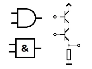
Here you can see the AND-gate circuit.
The output (right) is only Vcc, when all (You can add more, if you want) transistors are on.
The disadvantage of this build, is that every transistor or diode, has a voltage drop of about 0.4 to 0.7 Volt.
This fact adds up, if there are many gates, which feed the next gate and so on.
At a specific point, the voltage which should turn the gate on, is even less than the threshold voltage.
Maybe you can see the problem now.
This logic gate is off on the output, even if one transistor is conductive and the other is driven with 0.5 Volt.
Now you can imagine, how hard it was to find the troubles.
Measuring each logic-gate, still gave me some voltage, but with a little less than Vcc.
I don't feel comfortable, by posting bad full-adder schematics, but you should know how NOT to build an adder:
I works fine for one chip, but doesn't, with a lot of them in series.
Same here. By the way, I had no 0 bridges in 2013. (And a bit less routing skill)
The second try of an 8 bit full-adder:
This version is much better, compared to the first build. It used my NOR standard and works fine.
But the logic unit, on the other side, is still not lovely.


