Reverse engineering of a parking sensor
January 25, 2018
I wanted to hack such a parking sensor kit for a car.
I asked myself, how could I make something more complicated and useful out of it?
There are 2 posts about such projects in the Internet, but they didn't work for my parking kit.
Let's begin:
Such a parking module uses ultrasonic waves to detect objects.
In this case, there are 4 of these sensors. When the board is powered with 12VDC, you can hear the pulses which go away. (Like a soft rattle sound)
These modules are available with a small 7-segment display, a 4" Display, or only with a speaker.
(There are also some available with 8 sensors)
I bought all versions multiple of the parking sensor kit, to test which one is the best for hacking.
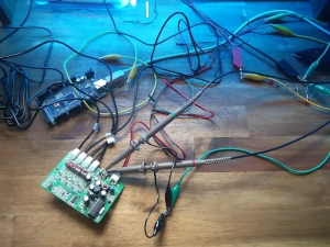
I connected an oscilloscope to the pins, to see what happens.
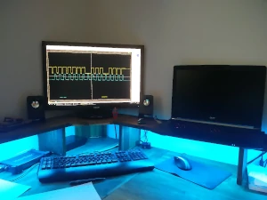
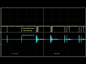
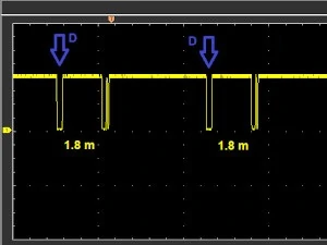
This picture above is one of the signals, which are sent to the 7-segment display continuously.
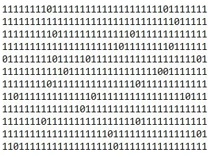
With an Arduino, we evaluated the string of data:
Anyway, it looks promising:
my brother and I googled the name of the two ICs in the 7-segment display. As assumed, they are 8-bit shift-registers.
Neither catching the signal pins for the display, nor analyzing the bits doesn't seem to work.
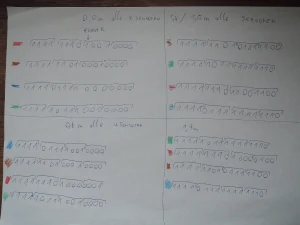
(We thought, that the first byte was the sensor-ID and the rest some encrypted data)
It took us about 4 hours to recognize, that this is not a distance or something similar in binary.
The green wave (on the first picture) is a clock signal, which activates the shift registers in the display.
Of course, they are rising edge triggered.
Even the length of the gap, between the yellow binary waves, has nothing to do with the distance.
The problem was, that the gap slightly changes by the distance between an object and the sensor, so we got a bit distracted.
After much calculation, coding and brain work, we came up with a new idea:
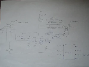
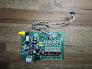
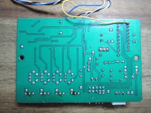
I reverse engineered the circuit board and searched for some datasheets for the ICs. (The big DIL IC is self-made)
The middle IC is a "4-channel analog multiplexer/demultiplexer" and the IC on the left side, a "Dual Low-Noise operational amplifier".
We called the self-made IC on the board "brain", because that is what it does.
(It converts the nearest "distance-time" into the bits for the output-LED, per side)
The brain sends every drive signal, two times. On pin 10, it receives the yellow signal.
The blue signal, is from the low noise amplifier. (The big bar is the sonic wave, which is sent to the piezo sensor.
The others are the echo)
At a real distance below 30 cm, the "brain" can’t calculate the distance anymore.
(Because the time between the sonic burst and the received signal, is too little)
For example, the HC-SR04 for the Arduino μC, can measure until 2 cm.
(But it is not waterproof and can not send and receive with one sensor or through a plastic cover!)
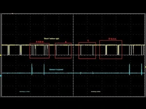
The routine is like this: AA BB CC DD AA BB CC DD and so on.
"scanning sensor A" is the generation of the ultrasonic wave in the sensor. And the "brain" gets the distance in ms.
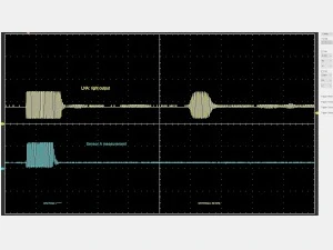
Here you can see a scan of sensor A, B and D.
The distance is about 1 cm. Far too little for the parking sensor module, but not for the Arduino and certainly not for the osci.
Details, we came up with:
- The minimum time to wait is 32,6 ms. (About 5 m back and forth) After this time, you can switch to the next sensor.
- The data string needs to be inverted and then you can see, how the "Brain" controls the LED's with the shift registers. (Unfortunately, it's no encoded signal)
- The distance is calculated of the rest charge of an e-cap.
- All the sent signals are repeated after 4 different 8 bit codes.
- The distance has to be read directly from the analog amplifier and must be compared with the clock signal, generated by the big "Brain".
Let's prepare the board:
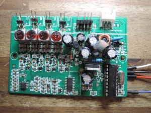
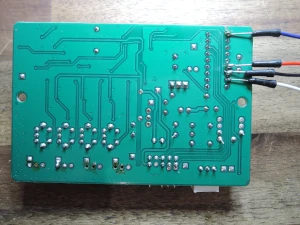
We need to take the signals for the μC like in the picture below.
These spots are after the LNA + some extra logic, so the signal is digital and ready to use.
With these 4 wires, we get the often used "SensorA, SensorB,.. etc." signals.
The fifth wire goes to pin 9 on the "brain" and is the "echo" signal.
New attempt to get the information:
(Which is more clear after the first inspection)
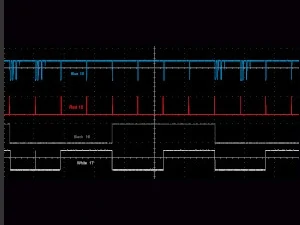
Signals out of these pins:
The pins 16 and 17 make the assignment for the 4 sensors.
Pin 15 displays the moment when the burst signal is generated. (IC enables the LC circuit)
Pin 10 is "zero" when the burst signal or the echo gets detected.
The only thing left is to detect the falling / rising edges and measuring the time between the burst and the echo.
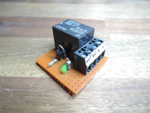
A small optional circuit for turning the devices on and off.
Overall, I bought 7 parking kits for testing
Now, you need a simple code for counting the time between the signals. (Echo and SignalA, Echo and SignalB, …)
Solder the shown IC pins (10,15,16 and 17) to a wire and connect them to the Arduino Pins.
Define them as INPUT and read the state with: digitalRead(Pin);
Pin 10 on the DIL IC gives you a "0" / "false" when something is dedected.
The burst signal gives a "false" too.
(Because it is all in one and the LNA receives it)
At this moment, you start to measure the time until a second "0" comes (echo from an object):
With Pin 16 and 17, you identify which sensor gets this echo back.
Because the burst signal goes to all sensors.
Conclusion:
It was very difficult to disassemble the board in his components, but it was fun trying it.
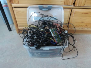
4 of the same model, are placed in my car for the real use of this hack.

