16 bit binary to decimal decoder
May 20, 2020
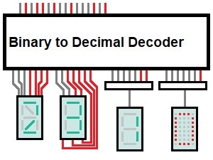
A simplified representation of a decoder:
Some key data first:
- 34 – 39 of these cards are needed
- Some logic will be strewn in between
- 5 – 6 BCD to 7 segment decoder are needed too
- 5 – 6 times a nice 7 segment display
The complete thing works parallel, thus it's very fast in processing data.
Maybe the whole part will get too big, but let’s wait and see.
Now the second prototype without these bypass tracks:
And this method is called double dabble.
It got invented in 1960 and can also be done by hand or without a paper only in your head.
I use the hardware version and is as follows:
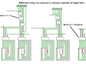
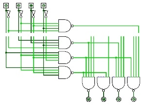
It is a circuit which adds 3 when the number is greater than 4. (add 3 if i >= 5)
Here you can see how it works:
The same circuit with the NAND NOR NOT standard:
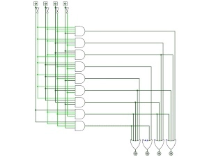
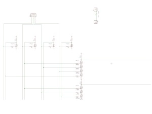
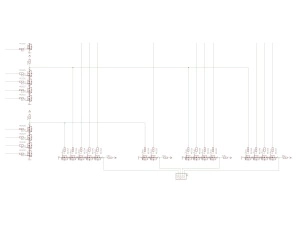
Schematic for this circuit:
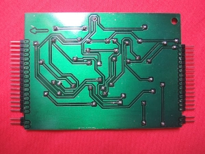
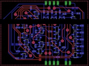
This is the PCB for the second prototype.
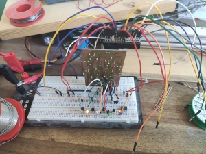
The setup for testing.
Maybe you did not noticed but the INPUT is 0110 (6). Because of that the OUTPUT is 1001 (6+3=9).
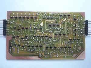
And the finished board. Tested, sealed and ready to use.
Unfortunately, a few mistakes have occurred:
The drill was too tiny (0,5 mm) and destroyed the copper around the pads. So I got an 0,8 mm drill now.

