Program counter
September 23, 2021
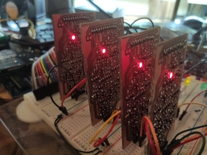
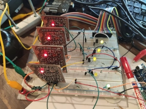
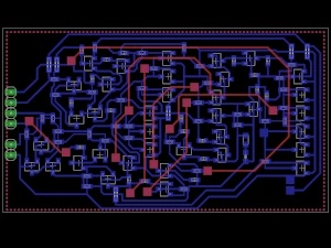
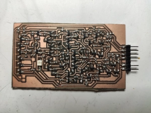
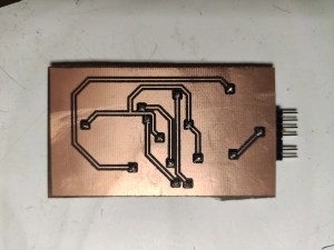
This a a part of the program counter.
Eight of these would be great because then I have 256 lines of possible machine code.
Each line has a set machine code
My instruction pointer (many names are possible) has the memory address of the current statement/instruction stored. Every address is split into a unique output with a decoder. This output will power a word line in a read-only memory.
The yellow LED is showing the state of each counter module. (The green LED is the clock signal from the Arduino)
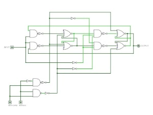
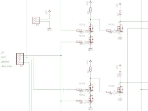
The logic design of a module.
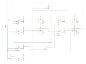
The schematic of a module.
The program counter is able to jump to a specific address. This is necessary if you want a for/while-loop, an if-else conditional or a subroutine.
A simple goto is also possible. And it is important to save the starting-address for some commands.
Update October 13th 2021
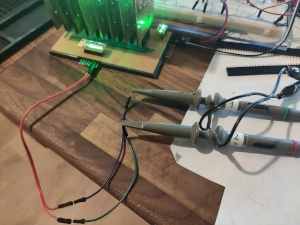
I made a total of eight pieces and changed all LEDs from red to green. Printed a roof and a base plate for the counter.
Then I took my oscilloscope and displayed all outputs.
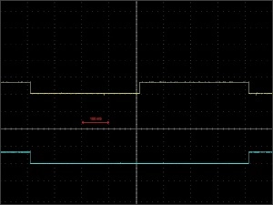
Each module responds to the falling edge.
And as every full-grown binary counter, also this one halves the previous signal frequency.
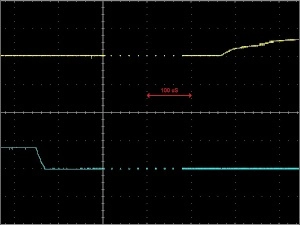
Yellow is the first oscilloscope probe.
This delay is due to the fact that the signal has to travel through 4 logic gates.
The following circuits have to be designed so that these "not allowed conditions" do not cause any troubles.
The weak edges are because:
- I only use n-ch Mosfets. (And not combined with p-ch.)
- Each Mosfet has to discharge its electric field through a 47 kOhm resistor.
- And each Mosfet gets charged through two 47 kOhm resistors.
The future will show if these slow rising edges are acceptable.
The falling edges are slumping and are looking quite well.
I even already have a solution for the long delay. (If this causes a muddle.)

