4 bit Decoder
September 27, 2015
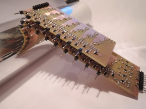
This decoder is used to address the 16 byte RAM.
A typical decoder has n input pins, an enable pin and 2n output pins.
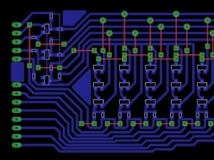
In the picture you can see the 16 output pins, the 2 supply voltage pins,
then comes the enable pin (Vcc = ON), at last the 4 inputs.
(Until 2017, I made all my circuit boards with GND on the left side)
You could omit the enable pin, but then you would only have 15 outputs.
Because all the outputs would be zero, when the binary "0 0 0 0" is applied.
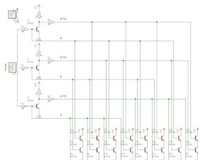
Here you can see an 3 bit decoder circuit. (The 4 bit decoder works the same way)
The only problem with this design, is the triple AND gate at the bottom.
But the output voltage is still enough high, when operating with 5V (5V – 2.1V)
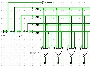
4 bit to 16 addresses, with the new NOR design.


